-
Signal Coupling and Simulation Feedback
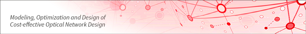
Amplifier placement may be required due to fiber and (R)OADM losses. To assess the WDM
system performance, we can use the signal metric maps displayed for a particular transmission line
()
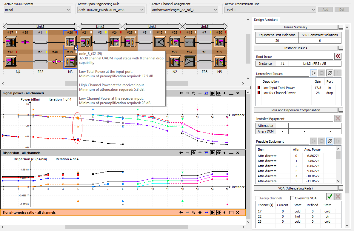
and a system performance summary table, as shown in
.
In this particular design, no compensation of accumulated chromatic dispersion is required due to short optical
channel routes and wide operating ranges of the selected transceivers.
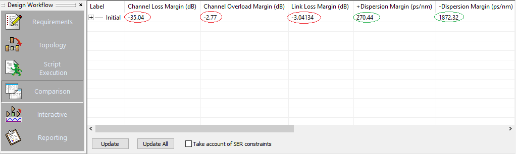
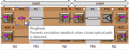
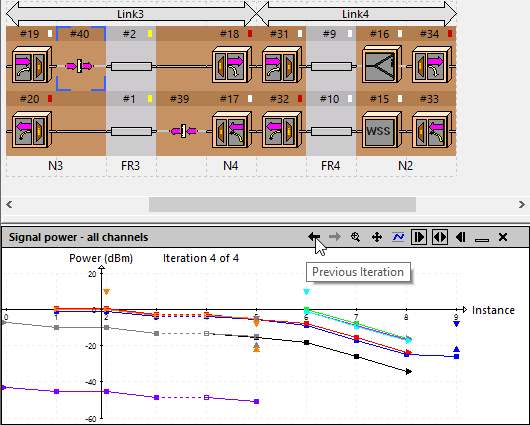
Closed optical paths may exist in complex mesh networks or simple rings, as shown in
.
To prevent simulation feedback caused by such paths and to calculate signal metrics, VPIlinkConfigurator engine makes the network topology graph
acyclic and computes the signals iteratively until a steady state is reached, as shown in
and .
-
Iterative Simulation and Target Power mode
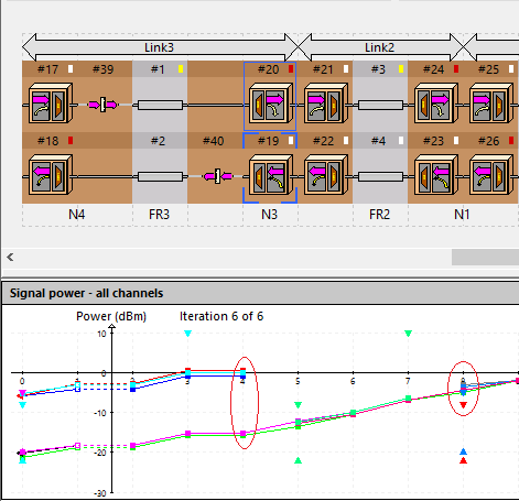
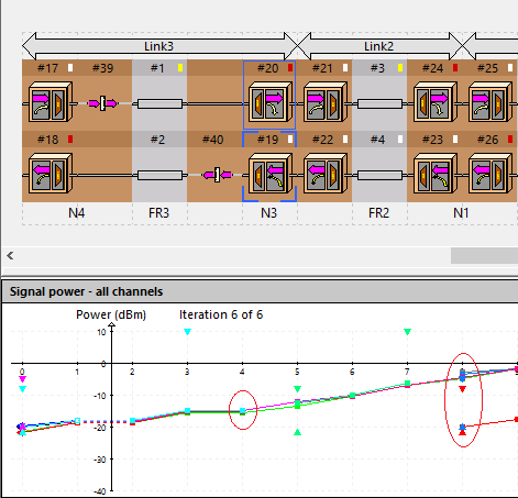
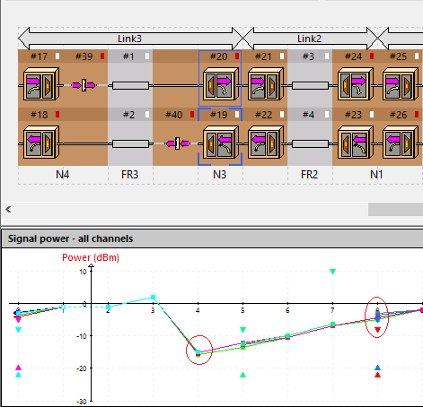
Design refinement typically starts at a point with no channels
passing through, e.g. at a terminal node. However, in ring or mesh networks with closed optical paths, inserting an
amplifier or attenuator causes changes of a signal at the points configured previously, e.g. an equalization of power levels of added and
express channels in one link changes the power levels in a link configured at a previous step, as shown in
and
.
In other words, equipment readjustment is required at the points configured earlier.
The Target Power mode fixes power levels at the points where closed optical paths are broken, and switches off iterations. Setting a
particular power level as an initial guess at the ring break points simplifies the design refinement process and
prevents iterative reconfiguration steps
().
See the next section for more information about manual link loss compensation.
-
Further Information
Keywords: Ring Topology Design, Closed Optical Path, Simulation Feedback, Target Power,
Iterative Simulation, Optical Power Equalization, Amplifier and DCM Placement, DWDM Mesh Network
See also the WDM Network Design application example for more
information about link loss and accumulated chromatic dispersion compensation.