GUI based Capture of Physical and Logical Topology

  • Description

    The task of designing optical transport systems and selecting equipment is often quite cumbersome with complex network topologies, channel plans and equipment configurations. Eventually every individual has their own version of the equipment datasheets and also their own methodology for building the network. VPIlinkConfigurator (LC) offers a simple approach to unify and control each step of the design process.
    This example focuses on the starting point of the design workflow: assigning the physical topology and traffic demands. Let us consider a quite simple network with several branches and one ring as an example. It includes 14 nodes and 13 optical channels. See Optical Link Configuration and Engineering examples for more information about nodes, links and traffic demands or channels.

  • Assignment of the System Requirements and Design Methodologies

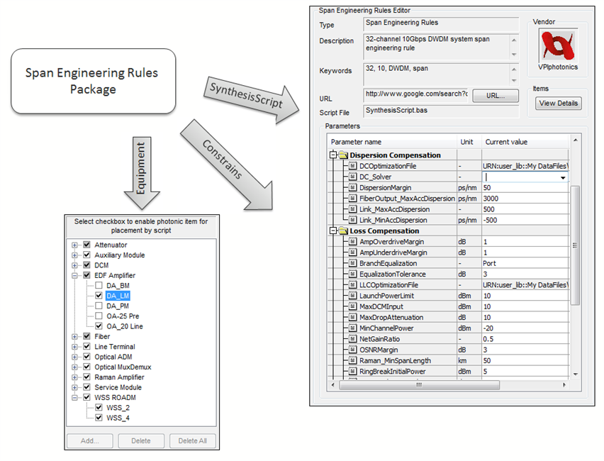
    Designing optical systems in LC typically starts with selecting a Span Engineering Rules (SER) package which includes:

    • System design constrains, e.g., future channel capacity, limitations imposed on accumulated chromatic dispersion, receiver margins, etc.

    • Passive and active optical equipment, e.g., OADMs, DCMs and amplifiers.

    • Optical link engineering methodologies are realized in a synthesis script which performs link loss and dispersion compensation, places amplifiers, DCMs, attenuators to meet the system requirements and constrains.

    Figure 1 shows some details of the SER package selected for this particular example.

  • Creation of the Physical Topology

    A graphic topology editor allows the system designer to easily manipulate the physical topology either to create new links and nodes or to connect the existing nodes, as shown in Figure 2.
    Automatic creation of the fiber plan is realized using the Application Programming Interface (API) of LC. Figure 3 shows the interface of a simple macro which configures fibers automatically.
    The appearance of the physical topology can be modified manually or via the API. Figure 4 shows the result of a simple script written in Basic.

  • Creation of the Logical Topology

    Once the physical topology has been defined, the logical connections between any two nodes in the network can be assigned.
    The logical connection or traffic demand between two nodes can be easily established using the VPIlinkConfigurator GUI. Such important parameters of optical channels as signal rate, bit rate, number of channels in the logical connection, the start and end nodes are specified while the connection is being built. A GUI based creation of optical channels between two nodes is shown in Figure 5. If there is only one path from the start to the end node, the channel route is established automatically. The capture of physical topology with specified traffic demands is shown in Figure 6.
    Once the traffic demands have been specified, physical paths for primary channels and protection channels can be established. See the next step of the design workflow for details.

  • Possibilities

    • VPIlinkConfigurator allows for import of network topology data along with GUI based capture of the physical and logical topology.

    • An evolution of optical network can also be planned using VPIlinkConfigurator. For example, new physical and logical connections are added to the existing configuration, and the performance of a new network design is evaluated.

    • Equipment can be inserted and configured manually, for example, fibers can be pulled out from the Photonic item palette and dropped into a certain fiber route.

    • VPIlinkConfigurator offers several algorithms for automatic channel routing.

    • GUI capabilities of VPIlinkConfigurator also allow for manual routing of optical channels.

  • Further Information

    Keywords: Optical Network Design, Fiber Plan, Traffic Demands, Future Channel Capacity, Primary Channels, Protection Channels, Optical Channels, Link Design Rules, DWDM Network Simulation

    Examples describing other steps of the design workflow are available in the WDM Network Design section.

« back to other examples