Equipment Configuration in Ring and Mesh Network Designs

  • Overview

    VPIlinkConfigurator provides a workflow for all steps of DWDM network design. For a specification of physical and logical topology, and a configuration of add/drop equipment, see other application examples, e.g. WDM Network Design.

    This demonstration is focused on link loss and dispersion compensation in ring and mesh network designs and showcases such features of VPIlinkConfigurator as engineering constraints, problem area notification, and the Design Assistant mode. The latter simplifies and accelerates a manual configuration of amplifiers and dispersion compensation modules. The starting point of this demonstration is the initial configuration which includes the physical and logical topology established (Figure 1 and Figure 2) and the add/drop equipment configured, as shown in Figure 3 and Figure 4.

  • Further Information

    Keywords: DWDM System Design, Add/Drop Equipment, Wavelength Utilization, Fiber Plan, Amplifier Placement, Channel Power Equalization, Design Automation, Application Programming Interface (API), Dispersion Compensation, Link Engineering Rules, Design Constraints, Ring Simulation

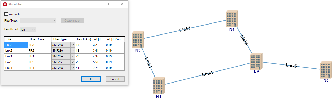
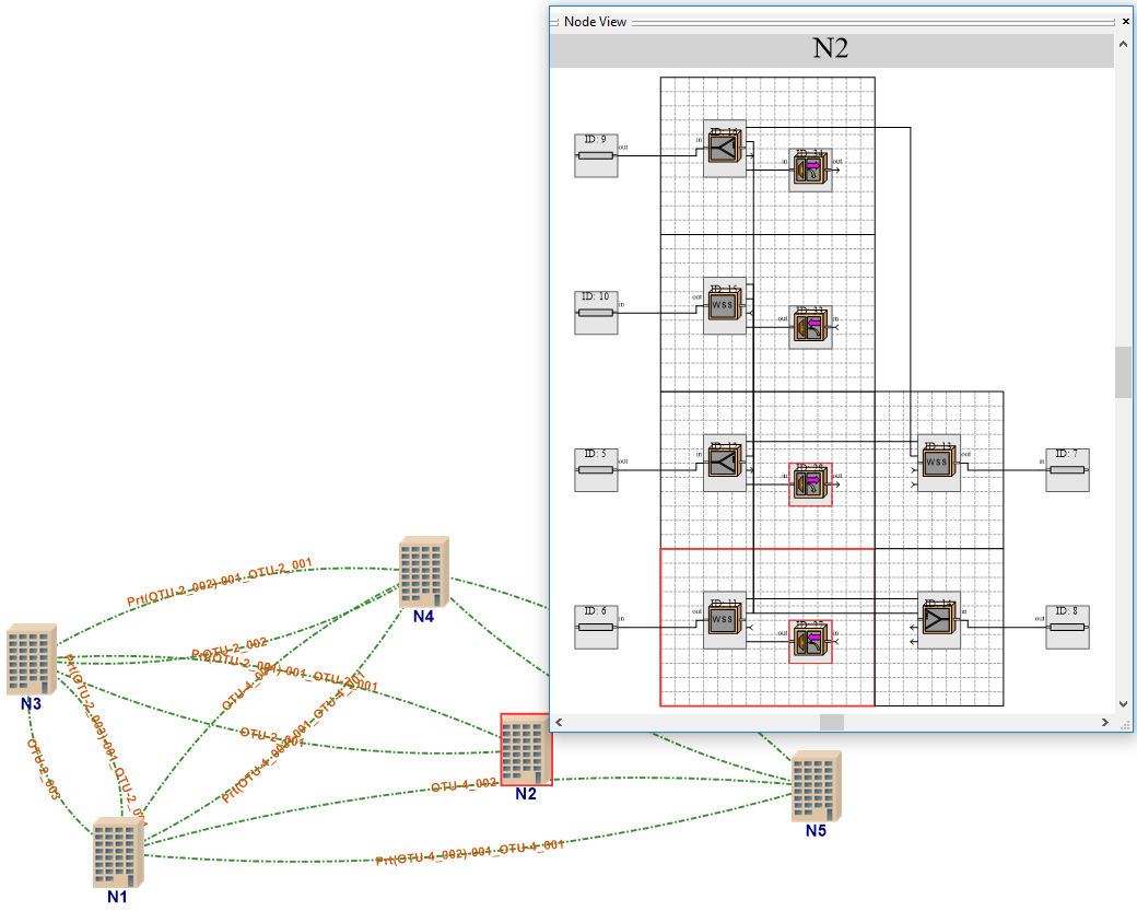
    See also WDM Network Design application example for more information about establishing fiber plan and wavelength assignment.

« back to other examples